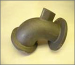
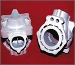
Pattern is a replica of the object to be cast, used to prepare the cavity into which molten material will be poured during the casting process.

Patterns used in sand casting may be made of wood, metal, plastics or other materials. Patterns are made to exacting standards of construction, so that they can last for a reasonable length of time, according to the quality grade of the pattern being built, and so that they will repeatably provide a dimensionally acceptable casting.
However with the advances in computing capabilities and Solid Freeform Fabrication technology (SFF) have made the designer's or patternmaker's 'science fiction' fantasy a reality for many part designers. All the designer needs to do is complete a three-dimensional (3-D) computer-aided design (CAD) model of the required shape and he has to click on a print icon.
SFF technologies use computer graphic representation and simple stock material to fabricate complex parts. Fused Deposition Modelling (FDM)2, Laminated-Object Manufacturing (LOM)3, Selective Laser Sintering (SLS)4 and 3-D printing5 can create functional parts in production materials ranging from plastic and nylon to ceramic and powdered metals. And with advanced computer numerical controlled (CNC) machining, metal parts with complex external shapes can be easily produced in limited quantities.
But, for designers of metal parts with complex internal geometries like cylinder heads, manifolds or transmission housings, traditional foundry sand casting is still the method of choice for producing production-intent prototype parts for functional testing. This new desktop manufacturing paradigm remains a dream. To create their functional cylinder head, the designer will need to design a set of tools or patterns for conventional sand casting.
 They will need to design:
- Parting lines and add draft so the tool can be removed from the sand mould
- Core boxes for the complex sand cores that will create the void for the water jacket
- Prints to aid the foundry worker in the assembly of the cores to the sand mould.
Of course, the design of each of these components must consider appropriate shrinkage factors for the particular alloy she has in mind. She might employ many of the rapid prototyping techniques above to speed up the fabrication of the sand-cast tooling. The completed tools would then be sent to a foundry, where an experienced mould designer would design gates and risers to supply molten metal to the mould and permit the metal to cool without unwanted shrinkage. Even for an experienced mould designer, it will take several iterations to get a solid casting that is free from any porosity that might cause leaks from the water jacket to the combustion chamber. If a single miscalculation or mistake occurs, it is necessary to go back to the beginning to try all over again. It is no wonder that engine developers allocate months for each design iteration of a new engine.
However, designers are now discovering ways to apply SFF technology in the foundry to create even more complex metal castings in small quantities without costly and time-consuming tooling6. They have discovered that they can produce production-intent parts for functional tests in days instead of months by foregoing the design and fabrication of tooling until the part design is finalised. More design iterations are possible in less time. They can even test multiple concepts with different configurations or different alloys simultaneously. Furthermore, as the final part design is fully tested, mass production tooling is created only once and correctly the first time. Automated die cast tools for a typical automotive cylinder head can cost in excess of two million dollars. Every time a design changes, these tools must be modified or scrapped. By employing patternless casting, designers can better optimise their designs and eliminate hundreds of thousands of dollars in wasted retooling costs.
One technique for patternless casting, called SandForm, was pioneered by DTM Corporation. In this process, foundry sand mixed with an organic binder is formed into a mould using an SLS machine. The sand is deposited in a thin layer and the shape of the part is sintered with a laser beam. The mould, complete with integral cores, is built up one layer at a time. Molten metal is then poured directly into the mould. Once the metal is cooled, the mould is broken away revealing the near net shape part.
Another technique for creating moulds directly from a 3-D CAD design is called Direct Shell Production Casting (DSPC)7 and was developed by Soligen Technologies, Inc. DSPC uses 3-D printing to create a ceramic mould with integral cores. A thin layer of ceramic powder is spread and then an ink jet printhead deposits a silicate binder onto the powder in the shape of the part. After the shell is built, complete with gates and risering, the loose powder is removed and molten metal poured into the remaining shell.
Patternless casting, using either of these techniques, offers a variety of benefits to the designer. Early design concepts can be tested and compared with no regard to the undercuts, parting lines and core prints usually required in sand casting. Since no cost-prohibitive tools are created, multiple part configurations can be produced and tested simultaneously. Design modifications are easily accommodated in CAD and require no retooling. The time between iterations can be reduced by over 50%, allowing for better design optimisation and reduced time-to-market.


