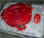
Large – quantity production of small castings requires match-plate patterns or more specialized types of pattern equipment. The cope and drag portions of the pattern are mounted on opposite sides of a wood or metal plate conforming to the parting line. Match plates are also integrally cast in which cast pattern and plate are cast as one piece in sand or plaster molds. It is used with so

me type of molding machine, in order to obtain maximum speed of molding. Advantages of the patterns are:
(a) Costly but good production rate
(b) Increase the dimensional accuracy
The match plate is the same as the mounted pattern with the exception that when you have part of the casting in the cope and part
in the drag (split pattern), these parts are attached to the board or plate opposite each other and in the correct location so that when the plate is removed and the mold is closed the cavities in the cope and drag match up correctly. The molding procedure is the same as a one sided mounted plate.
In most cases all the necessary gating runners, etc., are built right on the plate. The match plate might have only one pattern or a large quantity of small patterns.
The principle of the matchplate, meaning pattern plates with two patterns on each side of the same plate, was developed and patented in 1910, fostering the perspectives for future sand molding improvements. However first in the early sixties the American company Hunter Automated Machinery Corporation launched its first automatic flaskless, horizontal molding line applying the matchplate technology.
History:
The matchplate molding approach to green sand molding is one of two principle types of machine molding in use today. In the process, the cope and drag mold impressions are each formed on a side of a single pattern plate. The major advantage to this is that a single machine can make both cope and drag molds from one pattern (in cope and drag molding, separate patterns, and possibly separate machines, are used to make the mold halves).
Matchplate molding first became popular in the US as a way to replace small loose pattern work molding, where the low tooling cost for a single matchplate pattern could be justified for higher casting volumes. Because European adoption of this approach has yet to develop as extensively, the U.S. accounts for the majority of all matchplate molding production in the world.
Early matchplate molding involved the operator assembling a pair of removable "snap-flasks" together with the pattern, and then filling each side of the mold with sand, followed by a simple machine squeeze cycle to make the mold. Those early mold machines were generically called 'squeezer' machines (later equipment added a jolt action or simultaneous jolt and squeeze capability). After stripping the mold, the snap flasks remained at the machine for reuse and flaskless molds were delivered onto a mold handling system for pour-off and cooling prior to shakeout.
Since their introduction, automatic matchplate molding has continued to evolve to incorporate the newest technology and operational achievements. Following is a short timeline of events:
-
The design of fully automatic matchplate molding machines was introduced in the early 1960s. It incorporated aspects of filling sand onto the pattern face (riddled or slinger approach) plus hydraulic squeeze action to make 14 x 18 in. size molds;
- As the system got its feet wet, many other new features were introduced, including the blow method of filling the mold halves, although this method was a departure from the conventional squeezer molding technique, and acceptance in the industry was slow. Ultimately the transition allowed foundries to increase mold production from an average of 200-300 molds/ shift up to 80-100 molds/hr;
- In 1978, a larger 30 x 32 in. mold size automatic flaskless molding machine first became available;
- Matchplate molding machines began to integrate more features, including one with a sequential blow-fill, squeeze, core-set and strip cycle. This machine achieved a molding rate of 240 molds/hr;
- A mold tilt-up with vertical blow was incorporated into the design of matchplate molding machines in 1995. This design approach was instrumental in replacing many manual and older matchplate squeeze-molding operations throughout the U.S.;
- An extensive list of optional equipment has been developed over recent years to complement these machines, including automatic lubrications systems, pattern heaters and vibrators, automatic pattern and mold blow-off devices, automatic core setters and automatic pattern changers.
Opportunities: Today, matchplate molding machines come equipped with operator-friendly controls, which can make the difference between achieving the output of, high-quality, high-volume mold production or low productivity from the foundry. Touch screen, graphic PLC control panels with manual and automatic modes, plus startup and diagnostic programs also are featured regularly.
Database information also is available to the machine operator. PLC memory storage of tooling records for all operating parameters allows the machine settings to automatically be entered when a bar code reader identifies occurrence of a pattern change.
Reliable production records generated by or at the machine, with online feedback to central computers can improve efficiency and lower operating costs. Future trends in this area can be expected to include full operating manual information retrievable at the operator station and direct machine telephone/modem connection to remote offsite maintenance centers for trouble-shooting and reprogramming in real time.
Automated matchplate molding systems also create the opportunity to correct one area of weakness in many foundries--a lack of complete integration between the molding units and the operating system (such as mold handling, pouring, sands system logistics and core-pattern scheduling). The optimum production system is engineered for balanced logistical and material flow at all times, with real time interaction when stoppages occur or job changes vary the sand-metal-core demand. Computer simulation of operating conditions and requirements, prior to designing new molding facilities, is considered a necessity for future foundries to compete in world markets.
While integration of complete system control between all operating units is required, it is difficult when different suppliers manufacture the matchptate machine and individual system units. One possible solution is a project 'design/build' engineering approach with responsibility for control systems.
Improved productivity also is considered a factor in today's competitive environment. A major element is molds per hour (ultimately higher quantities of good castings produced per unit of production cost). Newer machine up times are reported to be more than 90% by the better-run foundries, due in part to the specification of OEM built-in diagnostics and orders for maintenance training by the machine manufacturer. Unfortunately, ancillary support equipment often is found to be responsible for much of the measured down time.
Foundries that are able to achieve a 5% improvement in overall system uptime at typical molding rates of 160 molds per hour (equivalent to 60 molds per 7.5-hour shift), can readily calculate the payback at a known profit factor per mold.
Other competitive benefits afforded by the matchplate molding approach include:
-
less required supporting equipment to be purchased and installed;
- generally less floor space than equivalent capacity tight flask system;
- lower energy costs due to less material handling required;
- reduced maintenance expenses.
Capabilities:
Modern matchplate molding equipment is capable of better mold quality, less shift due to machine-mold mismatch (in some cases 0.15 mm or less), consistent dense molds for less grinding and improved parting line definition. In addition, the machines are enclosed for a cleaner, quieter working environment with reduced operator exposure to safety risks or service-related problems. Reduction in casting scrap rate and lower casting cleaning room costs are parts of most economic justification models when new foundry equipment is planned.
Due to the variation in casting product requirements and other factors involved to make a mold- sand specifications and control, pattern tooling configuration, etc.- every operation has different parameters for what constitutes a quality operation. While the side blow-fill method adopted by most automated matchplate machine manufacturers has been in use for several years, there is disagreement throughout the industry as to whether all jobs can be made on these types of machines.
Sand, when distributed across the pattern face during side blow-fill, often results in 'shadowing' if the sand flow is obstructed or deflected by high profile pattern shapes. Also, deep pockets are sometimes difficult to fill with side blow compared to top fill. Each operator has his own opinion of what is the best.
The mold compaction capabilities on all matchplate molding machines have hydraulic pressures, some with proportional valve control of hydraulic cylinders. This allows for mold squeeze pressures ranging from approximately 85-145 psi, depending on squeeze piston size.
Mold hardness (density) from 85-90 is stated to be achievable on any of these machines. However, a range of hardness is required to suit different specifications for ferrous or nonferrous casting applications. Squeeze pressure should not exceed the limits of sand spring-back or cause deterioration of clay-water layers and sand grain fracture. Flexibility of machine settings also is important to make adjustments to mold height, blow pressures, and pattern strip/ draw rates, etc.


